With the extensive application of free-form surfaces, modern manufacturing industry has an increasing demand for five-axis machine tools. Five-axis machine tools can be divided into several types according to different structures: double turntable type, turntable plus swing axis type, universal spindle head type, etc. The two rotary axes of the universal spindle head type CNC machine tool are both located on the spindle. Since the universal spindle head adds two rotating axes compared to other types of spindles, its motion error greatly increases, and the relationship between the error sources also becomes more complicated.

In recent years, error modeling of various types of five-axis machine tools has become a hot research topic. For example, Zhang Hongtao of Shanghai Jiao Tong University conducted error modeling research on a double-turntable five-axis machine tool, and Shang Peng of Tianjin University conducted an error modeling study on a swing-head plus turntable five-axis machine tool. For universal spindle head type CNC machine tools, the international standard ISO 10791-6 proposes a spherical motion detection scheme for its motion accuracy. Based on this scheme, K.M.Mudith ADassanayake proposed a method of identifying its ten static errors through observation equations.
The above studies all use homogeneous transformation matrix (HTM) to model the error of five-axis machine tools. It relies on a large number of matrix multiplication operations, which requires a large amount of calculations. The physical meaning of the error model is difficult to understand. This article conducts modeling research on the universal spindle head type five-axis machine tool. By optimizing the coordinate system settings, a simplified modeling method is proposed, with simple mathematical expressions and clear physical meaning.
1. Establishment of spindle head motion coordinate system
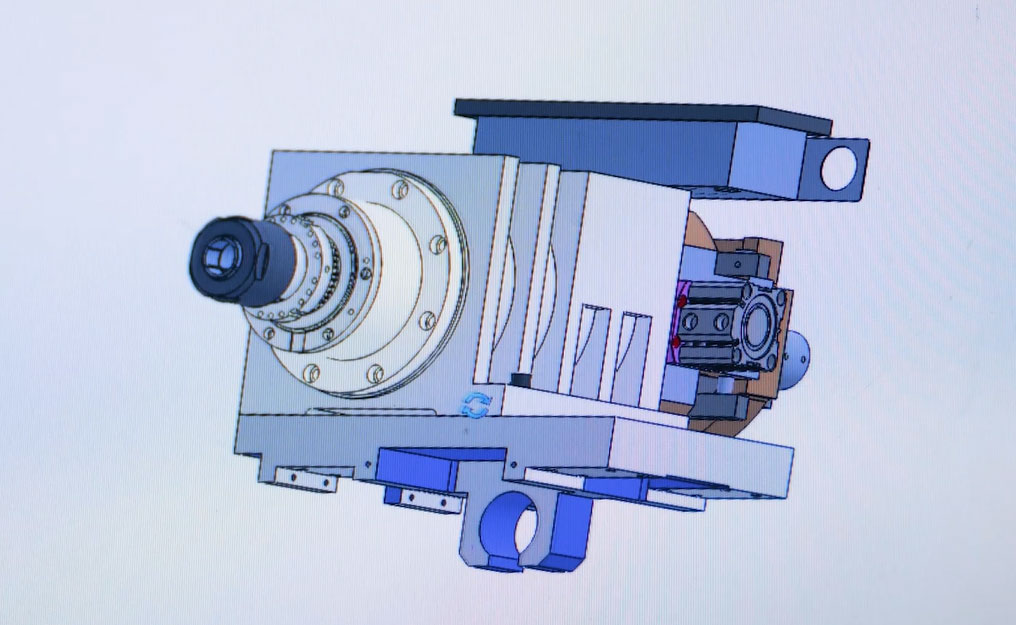
The structure of the universal spindle head type horizontal machine tool is shown in Figure 1.
Since this article only studies the error modeling problem of the universal spindle head, in order to prevent the introduction of other errors, the X, Y and Z axes are kept stationary during measurement, and only the A and C axes of the spindle head make rotational movements. According to the machine tool structure, the coordinate system of each component of the machine tool is established, as shown in Figure 2.
First, establish the machine tool reference coordinate system F (OF-XFYFZF). Because only the A-axis and C-axis of the spindle head move, and the X, Y, and Z axes do not move, we can regard the X, Y, and Z axes as being integrated with the machine tool bed. In order to simplify the coordinate transformation, we establish the reference coordinate system F (OF-XFYFZF) based on the intersection point O of the center line of the C axis and the center line of the A axis at rest (that is, the intersection point of the nominal C axis and the nominal A axis in the initial state). Obviously, we can establish the C-axis nominal coordinate system C(Oc-XcYcZc) on OF at the same time. In this way, the C coordinate system only has rotation transformation to the F coordinate system, but no displacement transformation, and the error transformation equation is relatively simple. However, we cannot establish the A-axis coordinate system on OF at the same time. Because the A-axis is the next link of the C-axis in the kinematic chain, the movement of the C-axis will affect the position of the nominal A-axis. As shown in Figure 2, the intersection point of the nominal center line of the A-axis and the C-axis center line has moved to the position of Oc''. We can only establish the A-axis nominal coordinate system (OA-XAYAZA) on this changed intersection point. In this way, the A coordinate system only has rotation transformation to the C'' coordinate system, but no displacement transformation. In Figure 2, the nominal coordinate system of the A-axis and C-axis is represented by a dotted line, and the actual coordinate system is represented by a solid line.
It can be seen from the above process that all five coordinate systems are established at the intersection of the C-axis centerline and the A-axis centerline, but this intersection has three different positions due to the different motion states of the C-axis and A-axis. . Therefore, the process of establishing the coordinate system of the kinematic chain tool ring can be summarized as “one intersection point, three states, and five coordinate systems”. An intersection point, that is, the intersection point O of the center lines of the two rotation axes. The three states respectively mean that both axes are stationary, the C axis is moving and the A axis is stationary, and both axes are moving. The positions of the intersection point O in these three states are different, and five motion coordinate systems are established at these three different positions.
2 Spindle head spatial error modeling
The machine tool kinematic chain consists of the tool ring and the workpiece ring. The kinematic error of the universal spindle head type machine tool is mainly in the tool tip point ring. The detailed analysis is as follows.
2.1 Tool ring error analysis
From the perspective of the sequence of motion transfer of the tool ring, the motion transfer relationship of each coordinate system is:
According to the sequence of tool ring motion transfer, error modeling includes processes such as position description, coordinate mapping, rotation transformation and differential transformation, as follows:
1) Location description
The position of the tool tip point is described in the tool ring end coordinate system A''. The nominal position of the tool tip point in A'' is A''TN. Affected by the thermal error, the error vector is expressed as A''δT,N(t). From this, we can get the description of the actual position of the tool tip point in the end coordinate system A'', that is
Let the distance from the tool tip point to the reference point be L. but
During high-speed rotation, the thermal error of the tool plays a significant role in the spatial error and cannot be ignored. Expressed as
2)Motion transformation
Because the five coordinate systems established are all at the intersection of the C-axis center line and the A-axis center line in different states, all motion transformations can be completed by differential transformation and rotation transformation.
First consider the transformation of the tool tip point position from the coordinate system A'' at the end of the kinematic chain to the A coordinate system. This is a differential transformation, consisting of differential movement transformation and differential rotation transformation, and can be expressed as
Among them, Aδ(α) is the error vector generated when the swing head A rotates through the angle α around the X-axis. It is the differential movement vector of the A'' coordinate system to the A coordinate system, which can be expressed as
And AA''R represents the differential rotation transformation of the actual coordinate system of the A-axis relative to its own nominal coordinate system. Based on the small angle assumption, AA''R can be expressed as
In the same way, the transformation of the tool tip position from the C'' coordinate system to the C coordinate system can be expressed as
In the formula: Cδ(γ) is the error vector generated when the turntable C rotates through the angle α around the Z axis.
CC''R is the differential rotation transformation of the actual coordinate system of the C-axis relative to its own nominal coordinate system, which can be expressed as
Finally, consider the case where there is only rotation transformation but no translation transformation between the two coordinate systems. According to the analysis in Section 2 of this article, we establish the C-axis nominal coordinate system (OC-XCYCZC) on OF and the A-axis nominal coordinate system (OA-XAYAZA) on OC'', so in the coordinate transformation we have Two rotation operators C''AR and FCR.
C''AR is the rotation operator when A rotates through an angle α around the X axis, which can be expressed as
In the same way, CFR is the rotation operator when rotating through the γ angle around the C axis, which can be expressed as
From the above analysis, it can be obtained that the position vector of the tool tip point in the reference coordinate system is
2.2 Workpiece ring error analysis
Although the reference coordinate system is determined, the position of the workpiece is often represented by the coordinate system on the workbench. Set up the X coordinate system at the center of the workbench. There is no relative motion between the X coordinate system and the F coordinate system, only a positional relationship. The installation error of the workpiece can be eliminated through tool setting and other methods and can be ignored.
According to the principle of translation transformation, we have
In the formula: FPOX refers to the position vector of the origin of the X coordinate system in the F coordinate system. With the advancement of CNC machine tool error measurement and compensation technology, errors in linear motion axes are becoming easier to identify and eliminate, and in comparison, rotational axis errors are much more significant than linear axis errors. Therefore, errors in the workpiece ring can be ignored.
2.3 Calculation of spindle head space error
The spatial error caused by the universal spindle head can be expressed as the difference between the tool tip point position vector and the workpiece position vector as
So far, we have completed the error modeling of the five-axis machine tool universal spindle head.
3 Case studies
For the universal spindle head type five-axis machine tool shown in Figure 2, the formulas for the position error and direction error of the tool are derived:
4 Conclusion
A spatial error modeling study was conducted on the universal spindle head of a five-axis CNC machine tool, taking into account the impact of the motion error of the two rotating axes of the spindle head and the spindle thermal error on the spatial accuracy of the machine tool. According to the structural characteristics of the universal spindle head, a coordinate system setting method of "one intersection point, three states, and five coordinate systems" is proposed, which reduces the complexity of the error model. Through the differential transformation and rotation transformation of the coordinate system, the spatial error model of the universal spindle head is established, and combined with examples, the formulas of the position error and direction error of the tool are derived, which lays the foundation for further error identification and error compensation of the universal spindle head. Theoretical basis.


